FAQ
This section contains frequently asked questions by topic.
Dealer
No, it is not possible to connect two system pumps to the FertiMiX-Go!.
No, these measurements are part of a set of readings included with the EC and pH Smart Switches that are required for irrigation control.
Ridder can also provide a Moisture Smart Switch which measures the Volumetric Water Content (VWC), Electrical Conductivity (EC), and the temperature of the substrate slab.
Yes, In firmware version 2.6.1 and onwards it is possible to make a complete backup on a USB stick.
Ridder hosts all data in a secure environment and ensures continuous communication between the Azure cloud storage, the CloudBoX and the HortiMaX-Go! app. In addition, the apps for iOS and Android and the desktop version for Windows are constantly updated to comply with the latest mobile phone operating systems and Windows versions.
| Storage location | History Retention Period | Service Plan requirement |
|---|---|---|
| Panel pc | 2 weeks | No subscription required. |
| Online; App service (CloudBoX) | 3 years | Yes, App Service subscription. |
No, this is not possible.
There is no standard system; the HortiMaX-Go! is a modular system. The system requires specific types of Smart Switches in certain quantities based on the situation in your greenhouse.
Yes, we can supply an official bus extender (50508740 Moxa Repeater TCC-120I). This extender extends the length of the network by another 1200 m.
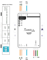
Figure 55: Wiring for HortiMaX-Go! bus extender.
Installer
-
Cabinets in the network are connected in series.
-
Stubs of the transmission line are not allowed.
-
The [A] and [B] signals are transmitted over a twisted-pair.
-
The [SGND] (Signal Ground) of the different cabinets are connected to one another over one wire of a twisted pair.
-
The [SGND] in a cabinet is connected to [PE] of that cabinet.
-
The [SH] (Cable Shield) is ONLY connected to [PE] in the controller cabinet.
-
The cable shields of incoming and outgoing BUS-cables in Smartswitch cabinets are spliced together and are NOT connected to [PE].
-
Both the outer ends of the network have to be terminated with a 120 [Ohm] resistor.
The Smart switch cabinets are connected within the BUS-system according to the general specifications of a RS-485 network. Refer to What are the general specifications of a RS-485 network:
Ridder can supply BUS cables with the correct specifications in various lengths, but other RS-485 cables can also be used. It is important that the intended BUS cable meets the following specifications:
-
Suitable for bus systems based on RS-485,
-
Twisted pair(s),
-
Shielded,
-
Characteristic impedance 120 [Ohm].
|
Ridder BUS-cable options: |
||
|---|---|---|
| Numberer | Bus cable type | length |
| 32002810 | UNITRONIC BUS LD 2x2x0.22 | 100 [m] |
| 32002811 | UNITRONIC BUS LD 2x2x0.22 | 300 [m] |
| 32002812 | UNITRONIC BUS LD 2x2x0.22 | 500 [m] |
| 32002820 | UNITRONIC BUS LD 3x2x0.22 | 100 [m] |
The maximum length of the RS485 BUS-cable in the installation is 1200 [m].
This length only applies when a suitable RS485 Bus-cable type is utilized in the installation. Refer to What type of bus cable do I use for the HortiMaX-Go! installation?
No, the BUS-signal in a HortiMaX-Go! installation is RS485.
Cat6 and Cat7 cable specifications do not comply to the General specifications for RS485 BUS-cable.
Make sure that a suitable RS485 Bus-cable type is utilized in the installation. Refer to What type of bus cable do I use for the HortiMaX-Go! installation?
Yes, Controller cabinets have separate terminal blocks for incoming and outgoing BUS-cables.
Therefor a Controller cabinet does not specifically have to be located at the start or the end of the RS485-bus.
Yes, the latest version of the Android app contains an active alarm message that will be sent to your mobile phone. This alarm contains vibration and push messages. In addition, the meteo (weather)/alarm card is equipped with an analog output that you can connect to a dialer.
No, and this is also unnecessary because the weather sensors are calibrated in the factory and normally do not drift. We do recommend cleaning the sensors and removing the dust and dirt twice a year, because this can cause measurement deviations. In locations with high dust concentrations, this should be done on a more frequent basis. Only use water to clean the weather station; do not use solvents.
No, and this is also unnecessary, because the sensors are calibrated in the factory. The sensors will, however, age. The rate at which this happens depends on the environment and the use of chemicals. We advise replacing the sensors annually or when there is doubt about the accuracy of the measurements. You can check the measurements with a calibrated portable T/RH sensor, but this does require a good test protocol.
Generic test protocol for sensors
The reference sensor must have at least the same or higher specifications as the working sensor (i.e., the sensor in use).
Comparing sensors:
- Take ten measurements with both the working sensor and the reference sensor at one-minute intervals.
- Calculate the average of the first five and second five measurements for each sensor.
- Compare the averages of each sensor:
- If the difference is T > 0.5 to 0.6°C or relative humidity (RH) > 2 to 3%, then repeat steps 1 - 3.
- If the difference T > 0.6°C or RH > 3%, then replace sensor.
- If the result is OK, then compare the average of the ten measurements taken with the working sensor to the average of the ten measurements taken with the reference sensor.
Checking measurement values can take some time.
No, this is not possible.
User
Yes, you can add more users using our Portal.
Check §5.4.1 Adding app user of the CloudPortal User Manual.
No, this is not possible.
Yes, receiving notifications is available within the Android app.
The app doesn’t include trend graphs as the controller does. This is by design. The climate status graphs need to be constantly updated and cause too much data traffic. That’s why we disabled them in the mobile app.
Our general response time is usually less than 10 seconds. If the response time is more than 1 minute, it may be due to the speed of internet connection of the system or the device.
In a prior version of the app, when automatic stage control was overridden by fixed position control, the automatic stages would be greyed out. In the latest version, the phases are not greyed out but remain white like they are still enabled. This is undesirable and will be corrected.
No, the graphs are standard.
This article is on our development backlog. It can’t be an full name, but the user would be able to select a single letter. A full name wouldn’t fit the screen / user interface.
This is an alarm that is triggered when the motor doesn’t respond (or doesn’t respond fast enough). It means the vent position measured by the sensor doesn’t match the vent position calculated by the controller.
No, the HortiMaX-Go! controller was designed for indoor growing and doesn’t measure rainfall.
This depends on the type of control. Vent control doesn’t use this feature.
This is a trend graph showing the calculated position over the last 2 hours. (See Tile body for more information.)
No, a pre-flushing function is not available in the HortiMaX-Go! Pre-flushing is possible with the CX500, the MultiMa and the Aqua CX300.
Technical issues and troubleshooting
80% of communication issues are caused by an incorrect cable type/connection or cable length.
At least 10% of issues are caused by inadequate grounding (earthing).
In less than 1% of cases, there is an actual problem with the equipment.
Recommended course of action:
Check the power supply of the Smartswitch(es)
-
Power supply must be DC24V.
-
DC0V of this power supply must be connected to [PE].
Check the BUS-cable type
-
Cable type must be suitable for bus systems based on RS485.
-
Twisted pair(s).
-
Shielded.
-
Characteristic impedance 120 [Ohm].
Check the connections of [A] [B]
-
Twisted pair [WH] = [A], [BN] = [B] (when recommended BUS-cable type UNITRONIC LD 2x2x0.22 is applied).
Check the signal ground [SGND]
-
The [SGND] (Signal Ground) of the different cabinets are connected to one another over one wire of a twisted pair[GN] (when recommended BUS-cable type UNITRONIC LD 2x2x0.22 is applied).
-
The [SGND] in a cabinet is connected to [PE] of that cabinet.
Check the cable shielding
-
The [SH] (Cable Shield) is ONLY connected to [PE] in the controller cabinet.
-
The cable shields of incoming and outgoing BUS-cables in Smartswitch cabinets are spliced together and are Not connected to [PE].
Check the network terminations
-
Both the outer ends of the network have to be terminated with a 120 [Ohm] resistor.
-
There should only be two termination resistors in the RS485 segment.
Check the BUS-cable length
-
The maximum length of the RS485 BUS-cable in the installation is 1200 [m].
-
This length only applies when a suitable RS485 Bus-cable type is utilized in the installation.
-
The RS485 BUS-cable length can be extended by another 1200 [m] applying a RS485 BUS-extender [50508740 Moxa Repeater TCC-120I].
Check the BUS-signal
Ridder advises to use a scope or ‘bus sniffer’ to measure /display the signal strength to check whether there is a clear signal.
Ridder service technicians use this device to examine all sort of network communication and buses. It’s very convenient and simple to use, and also very affordable. (For more information, click this link: PICO scope 2000 series).
Communication with the MTV-Go! Smart Switch tends to fail at some point and can then no longer be restored.
This is a known issue with the cabling and/or power supply rather than the Smart Switch itself. In most cases, it isn’t necessary to replace the Smart Switch.
See also: Why is there no communication between my system and the Smart Switch?
This issue sometimes occurs on the first series of MTV-Go!. The Smart Switches in the first series have a chip that can’t be updated. There hardly been any changes on the firmware of the MTV-Go!, so there is no need to update the PCB.
The Meteo-Go! may register slightly higher or lower values under certain circumstances. Cloud reflection in particular can affect the precision of the radiation measurement to a certain extent. This is due to the measuring range of the sensor, which is stated in the specifications.
To solve this issue: remove the radiation smoothing factor of 80%, but leave the delay time for opening the screen based on radiation. As a result, the shade screen will open based on the direct measurement data from the radiation sensor, rather than the smoothed radiation level calculated by the controller.
The controller should refresh the IP address automatically at a predetermined time (this is only relevant if you have a CloudBoX). Sometimes the controller will lose its connection and then no longer retrieves the IP address.
Rather than restarting the controller, you can refresh the IP address manually in the connection menu (you can find the Obtain IP address automatically setting by following this path  ).
).
This is caused by improper grounding (earthing) of the sensor. A new way of connecting the sensor (wiring diagram) can be found here.
Update the system to firmware version 2.5.1 or higher to resolve this problem.
Irrigation
The Smart Switches for alarms (and weather readings), the system pump and valves module.
A standard FertiMiX-Go! unit is equipped with an EC card for controlling two fertilizer channels and a pH card for controlling an acid channel.
This is equal to the number of valves. The maximum number of valves is 96; divided across 12 modules, each with 8 valve contact relays.
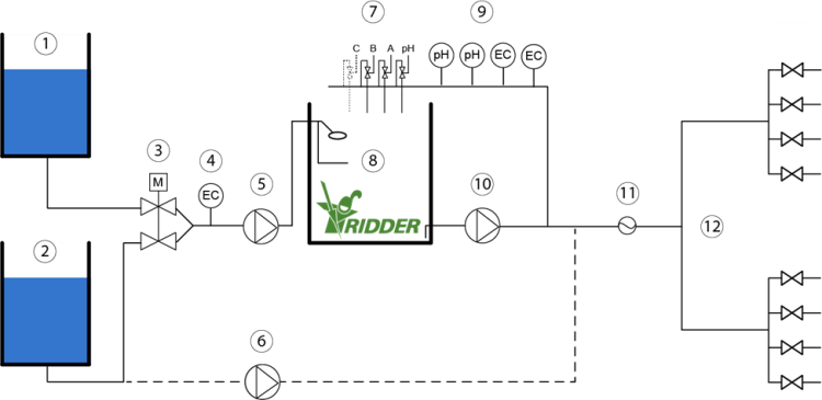
| No | Name | Description |
|---|---|---|
| 01 | Drain water | Drain water is the nutrient water that is not absorbed by the crop during cultivation on substrate. |
| 02 | Fresh water | Fresh water is supplied and can be mixed with drain water (1) before it is pumped to the Mixing tank, or the fresh water goes directly to the freshwater pump (6). |
| 03 | Supply valve(EC /Flow) | The mixing valve allows it to mix the drain water and the freshwater mixed based on the value measured by the EC sensor (4). |
| 04 | EC sensor | The EC sensor measures the value and transmits it so that the desired EC value can be mixed. |
| 05 | Filling Pump | The filling pump fills the mixing tank with a composition of drain and fresh water. |
| 06 | Fresh water pump | The Fresh water pump offers the possibility to use the fresh water for other purposes as well. |
| 07 | Dosing group | The dosing group ensures the mixture of fertilizers based on measurement of the EC and pH sensors (9). |
| 08 | Mixing Tank | The filling module regulates the water supply to the mixing tank. The water flows into the mixing tank via the filling module. The Mixing tank is filled with a composition of Drain and Freshwater and, if desired, is supplied with fertilizers by the dosing group (7). |
| 09 | pH EC Monitor / Control sensor | The pH and EC Monitor / Control sensors offer the possibility to monitor the EC / pH value to be able to set the desired amount of fertilizers. |
| 10 | System pump | The system pump pumps the water from the mixing tank towards the irrigation group (12). |
| 11 | Draw group | The optional flow sensor offers the possibility to also irrigate liters per minute in addition to watering based on time. |
| 12 | Irrigation group | The water flows into the irrigation valves which supplies it to the crops. |
Up to 4 fertilizers.
In the software, you need to set the fertilizer dosing ratio of each dosing channel; Different ratios can be set for each irrigation group. The dosing ratios indicate the proportion in which each fertilizer is to be applied by the dosing channels. The correct fertilizer mixture is achieved by opening the valves in pulses. Based on the EC setting, the controller will continue dosing fertilizers until the desired EC value is achieved.
This depends on the concentration, viscosity and type of fertilizers used.
No, but connecting a weather station does have many benefits. For instance, a weather station enables your GPS location to be detected automatically and irrigation to be triggered based on the solar radiation level (sunlight).
The flow rates of the fertilizer dosing channels can be controlled manually using a rotary knob. By default, the flow rate of each channel is set the to same maximum value. The control software creates the desired fertilizer mixture by opening the dosing valves in pulses.
There are three types of automatic irrigation starts: two based on time and one based on solar radiation. The cyclic time start can act as a maximum. If no other time start has occurred within the cycle time, the cycle time will act as a maximum.
Since the FertiMiX-Go! does not include settings for configuring the number of drippers, it is unable to determine how much water needs to be applied per dripper. There are valve group settings based on time and total number of litres. The latter is an option and becomes available if a litre counter is connected.
Yes, this is possible by setting up the valves as individual valve groups.
Yes, you can select a sensor from the calibration menu. This opens a calibration wizard that will guide you through the calibration process in four easy steps.
No, not with the HortiMaX-Go!. The HortiMaX CX500, MultiMa or Aqua CX300 do include this ability.
No, for now, each unit requires a controller.
Yes, but this does require the Pump Smart Switch.
Yes, it can. However, there are restrictions on the maximum irrigation volume in litres per valve group. This is currently 1000 litres per irrigation cycle.
At this time, the controller has no separate settings for an injection unit. It will therefore depend on the design of the injection unit.
The irrigation program requires at least one system pump and a valve card. A complete irrigation unit is therefore not necessary. However, the program is limited to one irrigation unit. This means that there is no point in connecting two system pumps; all valve cards will be connected to one irrigation unit.
If the unit may be busy with another irrigation group or waiting, the manual start command will be queued. The unit will start as soon as it is available.
Please note that multiple taps on the start button will trigger multiple irrigation starts.
However, the ![]() minimum pause time will apply. This setting, that is programmed for each irrigation group, prevents irrigation starts from occurring too frequently in succession.
minimum pause time will apply. This setting, that is programmed for each irrigation group, prevents irrigation starts from occurring too frequently in succession.
The interval between irrigation cycles is limited by the minimum pause time for the irrigation group.
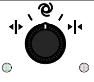
If the control knob of the system pump is set to 'manually off', then the pump is not available.
After a restart or power failure, the value entered for the radiation sum is not retained; it is disabled (- -). In the event of a restart or power failure, check the irrigation settings. If desired, re-enter the start conditions.
To enter the 'Start at radiation sum' setting, you can navigate this path (for example):  .
.
As from version 1.2.9, the 'Start at radiation' setting will be retained after a restart.
Climate
The standard sensor unit is the MTV-Go!. This is an electronic sensor unit for measuring the ambient temperature and humidity level inside a climate zone in the greenhouse.
Yes, a separate CO2 sensor unit is available that can be connected to the MTV-Go!.
No, each zone is equipped with one MTV-Go! and an optional CO2 sensor unit. Zones are assigned using the DIP switches. If two sensor units are assigned the same zone address, the controller will only be able to display the sensor unit with the lowest ID number.
Calibrating sensors in field level tends to yield highly inaccurate results. That is why the sensors have been designed so that they are easy to swap. We recommend calibrating the sensors regularly to continue to ensure accurate measurements.
The automatic ventilation program controls the vents based on the user-defined settings and certain indoor and outdoor measurements. In addition to the zone ambient temperature, the outside temperature and wind speed play a key role in the opening of the vents. The program calculates the optimum vent opening based on the above parameters and other variables, such as the humidity level. The calculated vent position may, however, be overridden under certain weather conditions (e.g. rain or frost).
Yes, there is a setting for this in the vent control menu.
The vents are controlled based on run time. If the limit contacts have been connected to the Smart Switch, the program can determine the run times automatically and will halt further adjustment of the vents at the positions 0% and 100%. If no limit contacts have been connected, the run time will need to be entered manually and the controller will continue adjusting the vents at the positions 0% and 100%.
Yes, unless limit contacts have been connected (and are engaged).
Yes, an offset can be set for each Smart Switch. This offset ensures that the controller will only start calculating the run time once the preset time has elapsed.
The system always synchronizes the vents positions at 0% and 100%. You can also program the controller to do this automatically at certain times of the day (up to 24 times a day). The controller will:
- open the vents when they are closer to 100%.
- close the vents when they are below 50%.
Two Smart Switches.
Yes, this is possible with five individual Smart Switches. This is also possible with only one Smart Switch if auxiliary relays are used. However, in the latter case no use can be made of the limit contacts control and the motor protection (PKZ) can only be read out as a group in series.
Yes, up to -20 °C.
Up to 32 Smart Switches can be connected to the HortiMaX-Go!. At least one Weather/Alarm Switch, and one sensor unit for each zone is required.
The Fan Smart Switch can only provide an ON/ OFF signal.
Yes, this is possible by carefully setting up the stages. The first step at cooling stage 1, then the second step and so on. The controller does not take the run times into account and does not alternate the fans.
Yes, a minimum pipe temperature can be set that is based on the humidity level. The HortiMaX-Go! also includes:
- automatic control based on the heating temperature.
- fixed position control based on the ambient temperature inside the climate zones.
- a general maximum position.
Yes, the preset humidity limits (overrides) have priority over temperature control. If the humidity level rises above the humidity threshold, then the preset humidification value will apply. See Stage control for more information.
The wind speed trajectory acts as an override on the vent position. If the wind speed rises above the preset start value of the trajectory, then the vents will not open further than the calculated maximum position. The calculated maximum position is determined proportionally between the start and end of the wind speed trajectory.
Example
- Start wind speed trajectory = 4.
- End wind speed trajectory = 8.
- Maximum position = 20.

To set the start and end values of the wind speed trajectory, you can navigate this path (for example):  .
.
The rain override on the vent position is applied immediately when it comes into effect. As from version 1.2.6, a delay time of five minutes will apply when it stops raining. This will prevent the vents from opening too soon once the override is cancelled.
You can look up your current software version in the configuration menu. To go to this menu, navigate this path on the display:  .
.
Check with your supplier for updates.
Yes, as from version 1.2.5, you can set the minimum time on and minimum time off. This will prevent erratic control behaviour. To set the minimum time ON/ OFF, navigate this path on the display:  .
.
If a hot air heater is oversized or located too close to the sensor unit, then the desired ambient temperature will be achieved very quickly and the start condition will no longer apply. Install the sensor units in a representative location and not too close to the hot air heaters.
The automatic (ventilation) program aims to apply the optimum vent opening based on ![]() measurements taken inside and outside the greenhouse.
measurements taken inside and outside the greenhouse.
The starting point in calculating the optimum vent opening is the preset temperature for the first cooling stage where the automatic mode has been selected. If a fixed value has been set for the first cooling stage, then it will apply. The automatic ventilation program will not use this stage for its calculation. See also: Automatic control.
The control speed setting allows you to program how quickly the ![]() automatic control function should respond to deviations from the desired conditions. Increasing this value (above 50%) will result in a faster response. Lowering this value (below 50%) will result in a slower response.
automatic control function should respond to deviations from the desired conditions. Increasing this value (above 50%) will result in a faster response. Lowering this value (below 50%) will result in a slower response.
To set the control speed, you can navigate this path (for example):  .
.
This the neutral stage.
Despite the indoor temperature being within the desired range (the so-called dead zone between too hot and too cold), a certain control action may still be required. For example, a fixed vent position or a minimum pipe temperature may apply during the neutral stage.
The pipe heating program works based on either a ![]() preset fixed pipe temperature or
preset fixed pipe temperature or ![]() automatically.
automatically.
The circulation pump will switch on when there is a heating demand. This means that the measured pipe temperature has dropped below the calculated value.
The circulation pump will switch off when the measured value rises above the calculated value.
To set the desired pipe temperature at which the pump will switch on, navigate this path on the display:  .
.
The fixed value of each stage acts as a minimum. After all, only the automatic control function can calculate a higher value.
If the preset maximum value is lower than the preset fixed value, then it will be given the maximum priority.
From high to low priority: gale override, rain override, fixed position, automatic control. The humidification and dehumidification stages apply as minimum and maximum values and take precedence over the calculated value of the cooling stage.
This means that gale and rain events always have the highest priority and will override all control.
Hardware
Yes, the secondary side of the Smart Switch contains relays that are suitable for both AC and DC (24V).
1 Ampère at 24 Volts, AC/DC.
The main control panel cabinet is fitted with a standard power supply that only supplies power to the Smart Switches in the main cabinet (up to 5 or 6), the panel PC and the CloudBoX. Other components, such as relays (which are controlled by the outputs) and other Smart Switches, require their own power supply with sufficient capacity.
Unlike other controllers, the HortiMaX-Go! is not equipped with regular I/O modules. Although this saves on infrastructure costs, it does limit the ability to connect analogue sensors.
No, this would entail serious security risks. A special CloudBoX has been developed for remote control.
No, in order to avoid the risk of overvoltage, we can provide special valve expansion cabinets. These ensure safe operation at maximum output.
In theory, this is possible. However, the HortiMaX-Go! controller will not detect an analogue switch used to operate the system. As a result, the controller will not be able to display the correct system status and risky situations may arise.
Yes, in that case the Smart Switch will act as an analogue switch.
Yes, but these have a longer delivery time.
No, the housing has been designed so that a fan is not necessary. The housing features natural ventilation and dual shielding to prevent sunlight from affecting the sensors. Another advantage is that this design minimizes the entry of dirt into the unit.
No, the Meteo-Go! uses a special bus protocol that other weather stations do not have.
The HortiMaX-Go! controller does not have any general purpose I/O ports. The control and measurement functions are performed by Smart Switches that were specially designed for this purpose.
Three Smart Switches.
Up to 8. There is also a limit to the amount of power that the valves may consume. If the power consumption of the valves exceeds the permitted maximum, auxiliary relays will be required to control the valves.
Not yet. We intend to offer various services with our HortiMaX-Go! cloud solutions, including data storage and an automatic export feature.
With our HortiMaX-Go! Cloud app, you can operate all of the controller's functions. Although, to avoid security problems and performance issues, this cannot be done directly.
Yes, the remote control connection is always made using a normal network connection and using a router. This should pose no problems if the router connects to the Internet with 4G. The only condition is that the controller and the HortiMaX-Go! CloudBoX are in the same network connected to the internet.
Although you cannot make backups yet, your data can be stored in the Cloud.
Ridder Growing Solutions adds updates to the support portal. The update file consists of a single file that needs to be copied onto a USB stick. After the USB stick is inserted in the OTG port and the controller is reset, the update menu will appear automatically.
The Meteo-Go! contains a GPS chip. This allows the unit's location and thus the astronomical times to be determined. Although the controller can enter this data automatically, you can also enter the GPS location manually.
Possible causes and solutions for this issue are:
- Your location is not set correctly. Either have the system detect your GPS co-ordinates automatically, or enter the correct longitude and latitude manually.
- The time zone offsets entered for winter time (standard time) and/or summer time (daylight saving time) are not correct. Check these offsets and adjust them.
Four irrigation periods and four climate periods. These periods can be set individually for each group or zone.
Yes, it is possible to use multiple controllers. The controllers can share the information from the same weather station. There is no communication between the controllers. The controllers are connected through a regular LAN network. A minimum requirement for this is a router with DHCP.
Each controller is assigned its own ID number that can be changed manually. This allows the controllers to be identified. There is no communication between the controllers, which is why the zones are not assigned consecutive numbers automatically.
Not yet, but we will be developing new functionality that will allow data to be exported from the Cloud.
No, all settings are accessible. The system configuration can be accessed by tapping the clock icon. The controls also have several configuration settings. Access to these settings is not restricted.
Limit switch feedback at 0 and 100% and / or a 1000-ohm vent position potentiometer.
Vent position potentiometers can only be connected to Smart Switches designed for that purpose. These Smart Switches are only available by special order and have a longer delivery time. As standard, the Smart Switches are equipped with inputs for limit switch sensors. These are normally connected with wire bridges. To connect the limit switch sensors, the wire bridges need to be removed.
Wiring instructions can be found in the inserts of the Smart Switch in question. The irrigation units come with comprehensive wiring diagrams.
For wiring diagrams, see Wiring diagrams.
This has not been determined. Rain will be detected when raindrops make a connection between the contacts. The rain detection sensor is always slightly heated to prevent condensation and fog from being detected as rain. A very dense fog may however cause rain to be detected. Once rain has been detected, the rain override will last for at least five minutes. This also applies if rain is no longer detected to prevent the vents from opening too soon.
Colour fastness value 6 - 7.
No, they are not. Only the LAN port can be used for a network connection.
Open - off - automatic - off - close. If the Smart Switch is in the 'off’ position, then the controller will not be able to control the greenhouse equipment automatically and no control actions will be sent to the relays.
Example
| 0% | 0-100% | 100% | |||
|---|---|---|---|---|---|
| Ventilation | closed | off | auto | off | open |
| Screen | open | off | auto | off | closed |
If a new IP address is assigned by the router, this is automatically processed by the HortiMaX-Go!.
The readouts screen will still display old data, because this data is retrieved only once. To display current data, you need to restart the HortiMaX-Go!.
Software
The following languages are available for the controller (as from 16-3-2017): Dutch, English, German, Spanish, French, Chinese, Polish, Korean, Italian, Russian and Turkish.
Yes, the HortiMaX-Go! app can be downloaded from the App Store and the Play Store. This app includes a demo mode featuring all operating elements.
Yes, you can view this here:  .
.
The radiation sum is not shown in joules in graphs.
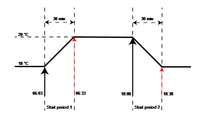
The preset temperatures can vary greatly between the time periods. For example: the cooling stage is set to 20°C in period 1 and 18°C in period 2. This means that the calculated temperature would need to jump from 20 to 18 degrees when the new period starts, resulting in a strong fluctuation in climate conditions. To prevent this, ramp-up and ramp-down times are used. These settings allow the temperature to be adjusted gradually (proportionally) to the new target value.
Example
Preset ventilation temperature
- Period 1 = 06:03 - 18:38 = 20°C
- Period 2 = 18:38 - 06:03 = 18 °C
- The ramp-up time and ramp-down time are both set to 30 minutes.
The ![]() stage delay time is the time that must elapse before the next stage may start. This prevents the controller from changing to new calculated values too rapidly if the zone ambient temperature is not stable.
stage delay time is the time that must elapse before the next stage may start. This prevents the controller from changing to new calculated values too rapidly if the zone ambient temperature is not stable.
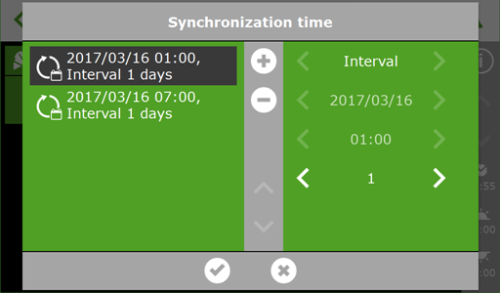
To correct a ![]() vent position deviation, the vents can be synchronized automatically. This involves adjusting the vents to the fully open position or the fully closed position. By triggering a long control pulse, it can be determined with certainty that the vents have reached the end position. Synchronization can be scheduled for each individual ventilation program. You can set multiple fixed synchronization times per day.
vent position deviation, the vents can be synchronized automatically. This involves adjusting the vents to the fully open position or the fully closed position. By triggering a long control pulse, it can be determined with certainty that the vents have reached the end position. Synchronization can be scheduled for each individual ventilation program. You can set multiple fixed synchronization times per day.
To set the synchronization time, you can navigate this path (for example)  , and then tap
  . The
. The ![]() Synchronization time screen will appear.
Synchronization time screen will appear.
Figure 56: HortiMaX-Go! Syncronization time screen.
The climate in the greenhouse cannot be controlled without input from temperature and humidity sensors; similarly, the ventilation system cannot be controlled without a weather station. This is called a 'dependency'. The software will be unable to build a configuration if these components are missing.
Cloud
The CloudBoX is the link between the controllers and the server. It collects all the updated data from the controllers and then stores this data in the cloud. The CloudBoX provides a connection between the controllers and the cloud server. The CloudBoX manages the data flow, which protects the controller from overloading. If multiple users are working with the controllers at the same time, then the CloudBoX will process this data flow.
Both the CloudBoX and the controller must be set to DHCP and automatically receive an IP address from a router (DHCP master). There is only one condition when it comes to choosing a location for the CloudBoX: it must be connected to the same network (range). A logical location is next to the router, but in principle any location is suitable. Make sure that the CloudBoX is connected to a reliable power supply.
The app will be available from the App store and the Play Store. The app can be downloaded on any Android or IOS device free of charge. The IOS app will follow once the Android app has been released.
To access the HortiMaX-Go! app, you will need login details. A web portal is currently under development. The owners of a paid cloud account will be able to log into the portal and manage users.
The app works in basically the same way as the HortiMaX-Go! panel PC. It has exactly the same features. The cloud capabilities will be developed further, to make it possible to export data (XML) for example.
- The controller has not been assigned an IP address. This may happen if the system restarts after a power failure for instance. Call up the IP address to check whether this is the case. If an invalid IP address is shown (for example: 0.0.0.0), restart the controller and check again. The connection will be restored automatically when an IP address has been assigned.
- The CloudBoX is offline or is in a different network segment than the HortiMaX-Go!. Check whether the CloudBoX is shown in the Cloud menu of the HortiMaX-Go!. If this is not the case, check the CloudBoX status by looking if the 2nd LED from the right is flashing regularly. If this is not the case, check the local network connections and settings to make sure that the HortiMaX-Go! and the CloudBoX are in the same network segment.
- Your Cloud account has expired. Renew your account on the user portal.
See also:HortiMaX-Go! offline in app.
Yes, the HortiMaX-Go! app is available worldwide, as long as you have an internet connection.
The HortiMaX-Go! app is available from the App Store and Google Play.
Dutch, English, French, German, Spanish, Italian, Polish, Russian, Turkish, Chinese and Korean.
No, this is not possible.
No, this is not possible.
Yes, it can. For more information, see the Internet connection for CloudBoX section.
You need to renew a CloudBoX licence before the expiry date. This will enable you to continue using the CloudBoX for another year. Complete the following steps to renew a CloudBoX licence:
- Click Basket
 . The CloudBoX window opens.
 - Click Add to basket + Start order process. The CloudBoX window closes. The Basket page opens.
- Complete the ordering process.
You have renewed the CloudBoX licence.
Follow the above steps on the CloudPortal. For more information about the CloudPortal , please see CloudPortal: Step-by-step instructions.
Disconnect the power supply from the CloudBoX for 10 seconds, and then restart it.
Tap and hold the system time for 3 seconds. Under the clock, a cloud icon appears. Tap this to see the serial number of the CloudBoX and the IP address. The serial number always starts with AABE and the year of production.
Tap and hold the I (information) button in the upper right corner for 3 seconds. A screen appears with two QR codes. Above this, the serial number of the controller is shown. The serial number always starts with AABD and the year of production. Go to the home screen in the app. This shows the serial number and the name of the controller (if you have given it a name).
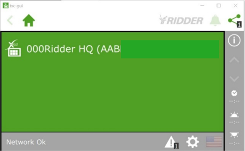
Figure 57: HortiMaX-Go! Serial number screen.
A user must be assigned to the controller. Click the link and go to step 5 on the web page: https://help.hortimax-go.com/en-en/Content/Cloud/check.htm.
If the user interface no longer works, this may have several causes:
On the home screen, look for the message with the controller number. If the Expired message appears before the controller number or the controller name, it means your licence has expired. Log in to the CloudPortal. This is where you can renew your licence.

Figure 58: HortiMaX-Go! Expired message.
Ten days before your licence expires, the Expiring message appears on the screen. You will still be able to operate the HortiMaX-Go!.

Figure 59: HortiMaX-Go! Expiring message.
Under the question ‘How do I renew my CloudBoX licence?’ you will find instructions on how to renew your licence.
The CloudBoX and/or controller are not connected to the Internet.
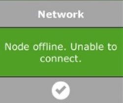
Figure 60: HortiMaX-Go! Node offline message.
Proceed as follows:
1. Reboot the router. If this does not have the desired result, complete steps 2 and 3.
2. Go to the Configuration menu. This is where you will find the setting for restarting the controller.
3. To restart the CloudBoX, briefly disconnect the power supply.
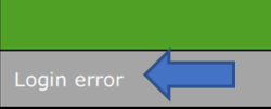
Figure 61: HortiMaX-Go! Login error message.
An incorrect password has been entered. If you enter an incorrect password five times, you will receive an e-mail and your access to the app will be blocked. You can remove this block using the Cloud Portal (see next point).
To unblock your access, first go to 'app users' on the Cloud Portal and click 'Temporarily blocked'. Remove the check mark next to ‘temporarily blocked‘ and save the setting. You can now log in to the app again, provided you enter the correct password. If necessary, you can click the small lock icon next to ‘app user’ to request a new password for the app.
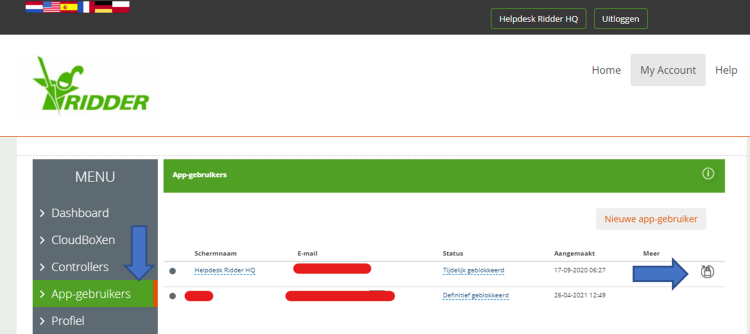
Figure 62: HortiMaX-Go! App users screen.
In this menu, you can also block a former employee from logging in to the system.
If the CloudBoX is not powered directly from the controller's USB port, but is connected via a USB adapter or a similar device, then the power supply may be slightly too low. This may cause communication problems. Check the communication LEDs of the network connection on the rear side of the controller. If the CloudBoX is operating normally, the green and orange LEDs will be flashing. If the power supply is too low, then one of these LEDs will be lit continuously, while the other will be switched off. If this is the case, proceed as follows:
1. Move the CloudBoX to the controller panel.
2. Connect the power cable to an USB port of the controller.
3. Install an extra network connection with an extra cable or a network switch.
After completing these steps, communication should be restored. You may need to restart the controller and CloudBoX to obtain a new IP address.
Restart the controller and CloudBoX to request the IP addresses again.
On the Portal https://portal.hortimax-go.com, you can find the expiration date of your CloudBoX under the ‘CloudBoXes’ header.
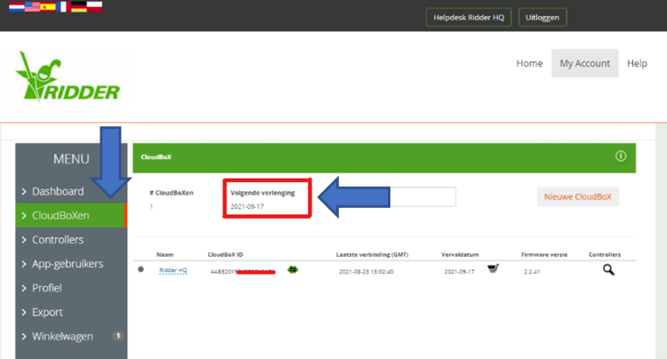
Figure 63: HortiMaX-Go! CloudboX screen.
No, this is not possible. We recommend linking your account to a fixed e-mail address, such as info@ or administration@ instead of an employee's email address.
No, only annual licences are available.
Yes, this is possible. If you request multiple licences for the same controller, these will be added to your credit balance.
You may not have entered a fertigation recipe. You can only start an irrigation cycle manually for a valve group that is in an active period and for which a recipe has been set. (EC, pH, volume in litres or duration of the irrigation cycle). Otherwise, a manual start cannot be initiated. However, it is possible to activate all valves in the configuration using a manual start.
No, only external starts are possible.
Up to 12 valve smart switches can be configured on the HortiMaX-Go!, each with 8 valve controls and 8 valve groups. This means that the maximum number of valve groups is 96.
The system requires a wind speed of at least 2 m/s after start-up to determine the wind direction. During this time, the system will continue to indicate ‘windward side‘ for both ventilation sides.
If, after 10 minutes, there is not enough wind to determine the wind direction, both sides are automatically marked ‘leeward side’. If the system has determined the wind direction, the correct indications will be shown automatically.
Yes, you can find the required software and instructions here.
Tap the system clock once, then tap the first tile, and then tap the third tile to check the firmware version and compare it with that on the help site.
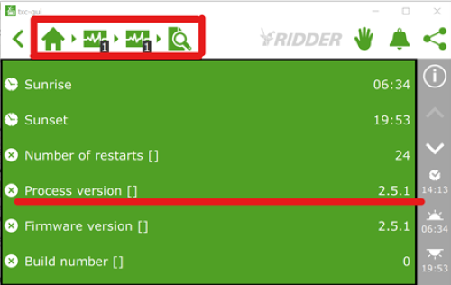
Figure 64: HortiMaX-Go! Firmware version shown on screen.
If the process version starts with a 1, you can update to version 1.2.20.
For versions that begin with a 2 (as above, 2.5.1), updates will be available regularly. New firmware versions will be published on the help.hortimax-go.com website.
Yes, this is possible in the Android app. Apple devices do not support push notifications.
This may be due to a slow connection, which means that the settings will take a while to load. If you get an empty screen and you tap the check mark instead of the small cross, you will load an empty configuration on the controller. If you wait a little longer or tap the small cross to close the empty screen, you will see the settings that you have set and your system will work properly.
In principle, you can install the CloudBoX anywhere, as long as it is connected to the same network as the HortiMaX-Go! controllers.
A standard USB port supplies the required 5 volts. You can also use the USB power supply of the controller itself if it is close enough to the CloudBoX. It is best not to use phone chargers, as they can cause problems over time due to a loss in power.
No, you cannot set a minimum pipe temperature on the HortiMaX-Go!. However, you can set a fixed temperature. This means that when the temperature is in the desired range, a fixed pipe temperature will be maintained.
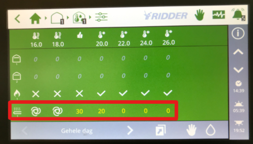
Figure 65: HortiMaX-Go! Pipe temperatures on screen.
No, this is not possible. Licences run for a whole year.
No, that is not necessary. The controllers must be connected to the same computer network and must have an identical controller ID. Each system must also be equipped with its own Alarm/ Weather (Meteo) smart switch.
No, this is not possible. Our invoicing process is fully automated, which means you can only renew and pay for your subscription via portal.hortimax-go.com. However, you can specify an e-mail address that you would like the invoice to be sent to. This doesn't have to be the email address that you used to create your account.
Your system will also work without a CloudBoX. However, you won't be able to operate the HortiMaX-Go! by using the app and the data export function will no longer work.
You do not need to cancel your subscription. Your licence will be cancelled automatically when it expires and will not renew automatically. When your licence has expired, a new licence will take effect from the date that the old licence expired. This means that if your old licence expired a year go, your new licence will cover the past year. To prevent this, please contact our help desk so that we can move the date forward.
Yes, the Alarm/ Weather smart switch has an alarm contact that you can use for an external alarm module or an alarm bell, etc.
Yes, this is possible. Each heating circuit is then assigned its own smart switch.
No, this is not possible.
No, this is not possible. You can only assign one sensor unit to a zone.
No, this is not possible. If you have any doubt about the accuracy of the MTV-Go sensor units, you can use a calibrated meter to check the temperature and the RH (Relative Humidity) measurements. If the deviations are too large, you will need to replace the deviating sensor units. The circuit boards are available separately (item no. 20800420).
Ridder Growing Solutions can also check the sensor measurements for you on request
No, this is not possible because a CloudBoX can only be registered once.
 .
. .
.